Hiraga 30W A class Amplifier

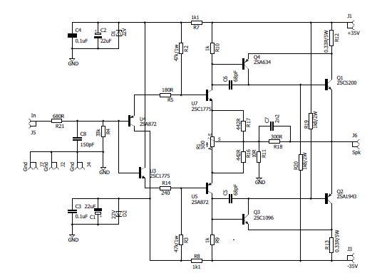 This is one of the most popular A class amplifiers. I used the original board layout shown in the magazine article (as well as the original driver transistors. However, due to the unavailability of the original power transistors, I opted for a more robust output stage using Toshiba 2SA1943 and 2SC5200 complimentary transistor pairs. This transistor change also allowed me to increase the rail voltage which allows the amplifier to deliver more power. However this build is for expirienced users because setup of this amp is not easy . I suggest this amp to be used together with very good power supply, Emi filter and if it is possible with speaker protection. The trimmer on board is for dc offset correction and it need to be slightly negative, however if you need to play with bias the best solution is to change 1W / 47k resistor to lower values eg. 33k or 27k . Instead of 2sa872/2sc1775 which were not easy to get you can try with bc550/bc560 . They are pretty cheap so even more I hardly suggest to get 100pcs and try to match them . First keep the transistors 6 secs in the DMM, then note the values and stick the trannies with the values close..
After this first step, when you have chosen the desired pairs measure them again, this time keep them for 12-20 secs till the HFE stabilizes on the DMM.
This matching will ensure you very low distortion at max volume and will help you adjust the offset really easy. For drivers I would suggest a higher HFE and FT transistors like 2sa1837/c4793 , but you can use any pair but with these aspects in mind: low Cob (max 35-40pf), high FT (70-100Mhz not more) and as much HFE you can.

Download:
How to setup bias on Hiraga
Method 1
a) first measure the 1k and 47k/1w resistors to be matched (THIS IS VERY IMPORTANT);
b) measure the 500r trimmer; the value should be fix 500r if not put resistors in series one for each end of the trimmer (not the wiper) to give this value; –this will help you balance elegantly the offset if the input is matched;
c)replace the 180/240 ohm resistors with 500R trimmers and set them at the values from the schematic respectively 180/240 ohm;
d) short the input and no output load and set the 500r trimmer at half;
e) set offset: it has to be between +0,045v ~ -0,005v;
f) measure the voltage across the 1k resistors, if it isn’t equal on both sides adjust from the “180/240” resistors values to have the same voltage across the 1k on both sides.. The voltage should be between 1,06v and 1,5v.
g) readjust the offset in the same limit after adjusting the voltage across the 1k resistors;
h) now measure the voltage across the 0,33ohm resistors; you should have between 0,495v or UP if you have decent cooling;
If the bias is not it the range specified above, then put a 100k double pot in place of the 47k resistors set to 47k for start up and after start up adjust accordingly.
If you have higher voltage psu than +-25v (specified in the schematic) or above 27v cc, increase the 1k8/2w bias resistors. I have a 27V cc psu and it was not needed to increase the 1k8 value… If you go higher you have to increase this value accordingly.
DO NOT decrease the 1k8 value to adjust the bias because even if it will decrease the bias a bit you will just increase the local NFB of the “Darlington” output arrangement which is not good. —I tried it, it worked, but didn’t listened to this mod…Than I reverted back to the original value;
Method 2
Another solution for bias adjust (if the above advices didn’t work) is to lower in STEPS the 1k resistor value to minimum 680ohm (don’t go lower), measure the voltage across it so that it will be in the parameters specified above (between 0,5v and 0,68v across it) and then readjust the 47k resistors to lower the bias..– tried this version with success.
Increasing the 0,33r to 0,47r value of the power resistors will also decrease the bias…