Hiraga “Le Monstre” 8W A class Amplifier D.I.Y.

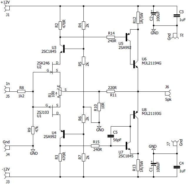 This is the schematic of the very popular small A class amplifier Jean Hiraga 8W.
The original Hiraga Amp transistor are replaced with 2SC1845+2SA992 and on output MJL21194G+MJL21193G which is the best replacement for originals.
The output transistors must be mounted on heatsink.
This amp has monster name not because of huge power it is because of current which is need for his proper work, so by my opinion power supply for all Hiraga amps need to be made with special attention.
Transistor inside schematics are not critical and it is possible when you build it to experiment with different variant’s bc550/bc560 , c1775/a872, c1845/a992 etc.
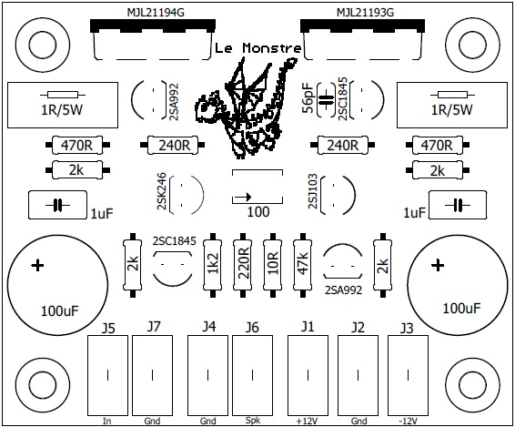
Trimmer on board is designed for current , however in this schematic amplifier worked from first time without any modifications. For those who want the most from his amplifier I could suggest fine current tunning to 600mA through resistors R2 and R3 usually it is value between 470ohm – 1k .
How to setup Bias and etc.
The procedure for seeting like 1 A current in output, can take some time.
For 8 Ohm speakers, this would be my initial current setting.
When you have 1 Volt DC across both 1 Ohm resistors, you will have 1 Ampere running.
What factors effects (most) how much current/voltage across 1 Ohm resistors?
Several things:
====================================
1. What JFETs you use.
And different exemplars of same 2SK170 /SJ74 can differ.
2. The potentiometer.
50 OHM or (47) pot = most current,
100 Ohm pot = normal
220 Ohm = less current.
3. Value of 1 k Ohm’s resistors.
Higher value = more ampere in output.
Lower value less current.