Dimmer v2
Infra Red Light Dimmer v2
 Infra – red light dimmer that you can see on these pages is improved version of Infra red dimmer presented on the site http://www.elektronika.ba/753/dvokanalni-ir-prekidac-v1/. For all your questions at your disposal is a forum which is tailored to users who understand Serbian:http://www.elektronika.ba/forum/viewtopic.php?f=3&t=8981A key element of assembly is Microchip’s PIC12F629 microcontroller, while the device can roughly be divided into three sections: rectifying, receiving and dimmer.
IMPORTANT: The construction of the device described above requires basic knowledge of electrical wiring. Since the current with which the inexperienced builder could possibly come into contact can be life threatening do not start construction without professional help.
If you have any other questions or concerns regarding the construction of the device please use to the aforementioned forums or space in the context of the page to leave your comments .
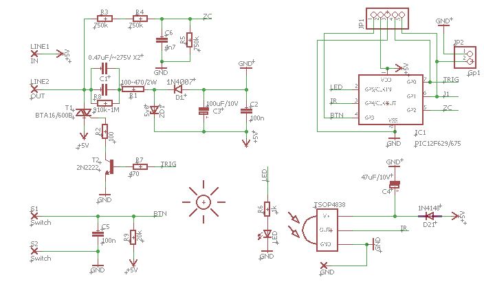
Displayed circuit represents infrared light dimmer with zero detection over bulb – zero-crossing. Rectifier part of the device consists of 0.47uF / 400V capacitor and 820 / 5W resistor, 100uF el. cap , 1N4007 rectifier diode and 5.6V zener diode. Pin 5 (GP2) serves to over two, in line, connected resistors, detect when sine wave passes through zero. Pin 7 (GP0) serves to turn on and off triac in the exact specified intervals achieving dimming effect . Pin 3 (GP4) is a data pin for infra-red receiver and it is responsible for receiving the binary code sent from remote control. Pin 4 (GP3) is a switch . SJ1 is a jumper that has to be disconnected for programming PIC12F629 microcontroller and after programming, this pin should be in the closed state.
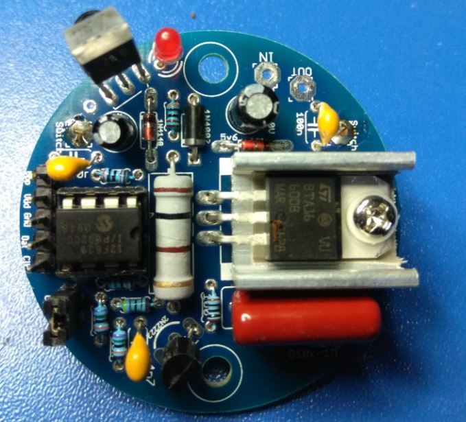
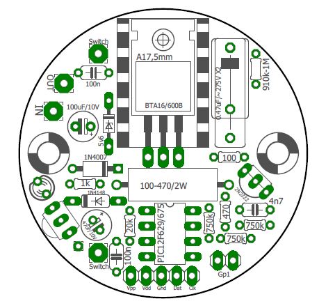
During the construction of this unit it is very important how you connect triac pins. The device is small enough for installing directly into the switch box in the wall.L-phase (line) need to be connected directly to the network voltage of 220V / 50Hz, while the N line is connected to the wire that goes to the bulb. As previously said N (zero) is received over the bulb so it’s important to say that this equipment is intended to be used ONLY on incandescent bulbs and device can’t work on LED, Fluorescent tubes or any other light sources….
The maximum power of the appliance depends on the strength of built-in triac but considering that in this version of the triac does not use the heat sink, we recommend that the device could not install the unit higher power of 400W.
The device is designed for direct installation on 220V / 50Hz network.
In the end I want say that the design of the pcb is customized for Slovenian manufacturer “TEM” wall bell switch .
Download: